For applications that require data computation and processing using field programmable gate arrays (FPgas), microprocessors, digital signal processors, and microcontrollers, it is important to ensure that the devices can operate safely and reliably. Since these devices can only operate within a certain power tolerance range, the power supply requirements are high. 1 Voltage monitor can be used to keep the system stable and reliable operation. In the event of an unexpected power failure, such as undervoltage or overvoltage, the voltage monitor can immediately trigger action to put the system in reset mode. However, it also faces some interference factors when monitoring the voltage in the power rail, which may trigger unnecessary misreset of the output. These disturbances include power supply noise, voltage transients, and burrs that may come from the power supply circuit itself.
This article discusses the different parameters in the voltage monitor that help solve these problems of power supply noise, voltage transients, and burrs. In addition, it will also discuss how these parameters can improve the reliability of the voltage monitor when monitoring the power supply to improve the reliability of the system in the application
Power supply noise, voltage transients and burrs in the system
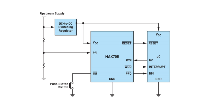
The power supply itself is flawed. There are always coupled noise artifacts in the DC circuit, which may come from the power supply circuit components themselves, noise from other power supplies, and other noise generated by the system. If the DC power supply is a switching power supply (SMPS), these problems may be more serious. SMPS produces a switching ripple that is related to the switching frequency. High frequency switching transients also occur during switching. These switching operations are caused by the rapid conduction disconnection of the power MOSFETs. Figure 1 shows the application circuit where the MAX705 monitor is used to monitor the output of the switching regulator (i.e. the voltage source for the microcontroller) for any problems.
Figure 1: The MAX705 monitor is used to monitor the switching regulator output, which is also the input voltage source for the microcontroller
In addition to the steady-state noise artifacts, there are also situations in the power supply where the voltage changes instantaneously to be obvious. During startup, a voltage output overshoot associated with the power supply feedback loop response is usually observed, followed by a period of voltage ringing until the voltage stabilizes. If the feedback loop compensation value is not optimized, this ringing can be more severe.
Voltage overshoot and undershoot can also be observed during transient or dynamic loads. In specific applications, sometimes the load requires more current to perform complex processes, resulting in voltage undershoot. On the other hand, reducing the load immediately or at a fast ramp rate will result in voltage overshoot. Power supplies may also have short-time voltage burrs due to external factors. Figure 2 shows that different voltage transients and burrs may occur in the supply voltage under different scenarios.
Figure 2: Voltage transients and burrs observed for supply voltages in different scenarios
There may also be voltage transients in the system that are independent of the supply voltage, such as transients in user interfaces such as mechanical switches or conductive cards in some applications. Switching on and off creates voltage transients and noise on the input pins (usually manually reset pins). All of these factors (power supply noise, voltage transients, and burrs) can inadvertently reach the monitor's undervoltage or overvoltage thresholds, and can also trigger false reset if this possibility is not fully considered in the design. This can lead to oscillations and instability, which is not conducive to maintaining a stable and reliable system.
How does the voltage monitor solve noise and transient problems to prevent false reset of the system? There are some parameters that can help shield transients related to the power supply or monitoring voltage. These parameters include reset timeout period, reset threshold hysteresis, and the relationship between reset threshold overdrive and duration. At the same time, transients associated with mechanical contacts in the circuit, such as push-button switches in manual reset pins, can also be shielded by using manual reset to set the period and the buffeting time. These parameters make the voltage monitor more robust and immune to transients and burrs, thereby preventing undesirable system responses.
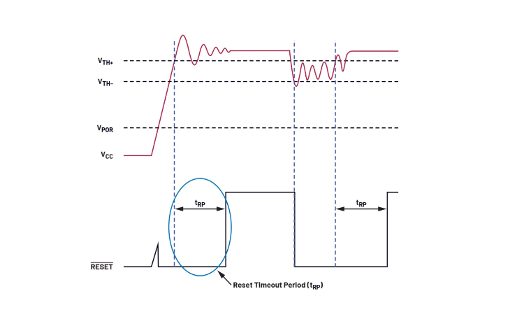
Reset Timeout Period (tRP)
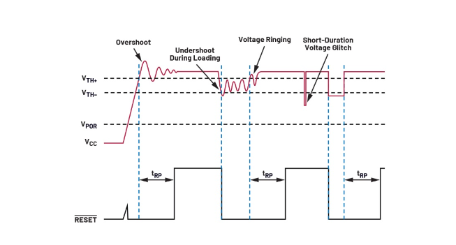
During startup or when the supply voltage rises and exceeds the threshold due to an undervoltage event, the reset signal has an additional period of time before it becomes invalid, called the reset timeout period (tRP). 2 For example, Figure 3 shows that after the monitored voltage (in this case, the supply voltage labeled VCC) reaches a threshold from the undervoltage or startup state, there is an additional delay before the low level is effective and the high level is invalid. This extra time allows the monitoring voltage to stabilize and shield overshoot and ringing before enabling the system or taking it out of reset mode. The reset timeout period helps improve system reliability by suppressing false system resets and preventing oscillations and potential failures.
Figure 3: The reset Timeout period (tRP) helps keep the system in reset mode while the supply voltage is stable
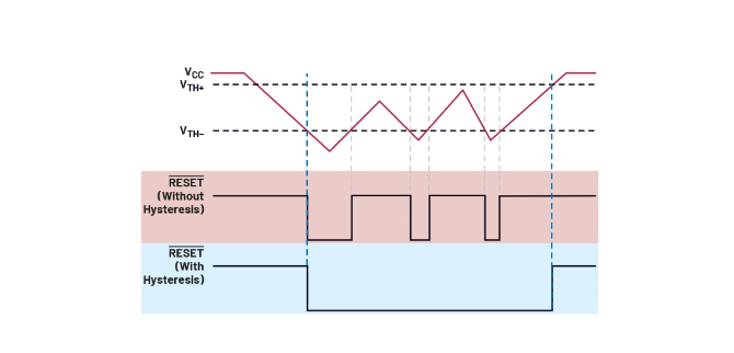
Threshold hysteresis (VTH+)
Threshold hysteresis has two main benefits. First, it ensures that the monitoring voltage has enough margin to exceed the threshold level before unreset. Second, it allows the power supply to stabilize before being unreset. When dealing with a signal with superimposed noise, the reset output may undergo multiple conversions as the power supply fluctuates and re-crosses the threshold region. As shown in Figure 4.3, in applications such as industrial environments, noise signals and voltage fluctuations can occur at any time. If there is no threshold hysteresis, the reset output signal will continuously switch between set and unset until the power supply is stabilized. This causes the system to oscillate. Threshold hysteresis eliminates oscillations by keeping the system reset, preventing the bad behavior shown in the blue shaded areas in Figure 4. This helps the monitor protect the system from triggering a false reset.
Figure 4: RESET output response without and with threshold hysteresis (reset timeout period not shown to focus on the effects of hysteresis)
Reset threshold overdrive and duration
Short - or long-term voltage burrs caused by external factors can occur in any system. There may also be voltage drops of different magnitude. The relationship between the reset threshold overdrive and the transient duration is related to the amplitude and duration of the voltage burr or overdrive. A short burr with a large amplitude will not trigger the reset signal setting, while a small amplitude and longer duration overdrive will trigger the reset, as shown in Figure 5.
Figure 5: A small but long duration burr will trigger the reset signal, while a short burr with a large amplitude will not trigger the reset signal
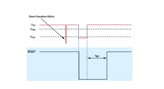
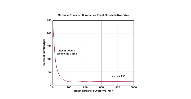
Depending on the burr duration, certain voltage transients in the monitored power supply will be ignored. Ignoring these transients will protect the system from disturbing resets, such as those caused by short-term burrs. These burrs may mistakenly trigger a system reset, resulting in bad system behavior. The relationship between reset threshold overdrive and duration is often presented in the product data manual in the form of a typical performance characteristic diagram, as shown in Figure 6. Any value above the curve will trigger the reset output, while values inside the curve will be ignored to prevent the system from missetting.
Figure 6: Whether the reset signal is set will depend on the magnitude of the overdrive and its duration
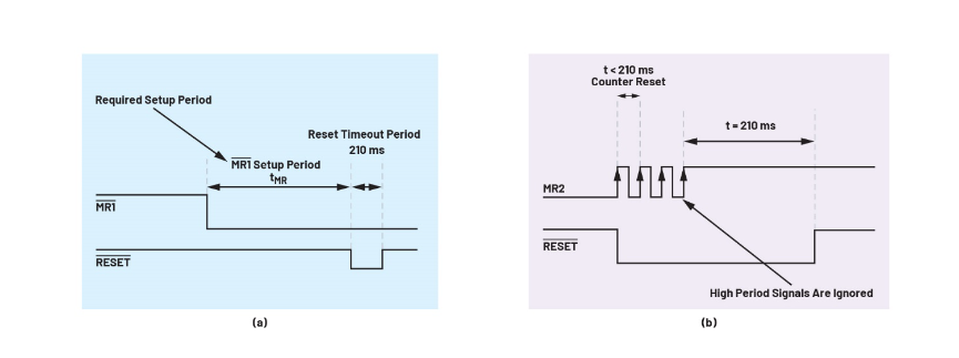
Manual reset Setup Period (tMR) and Shake off time (tDB)
The reset timeout period, the relationship between threshold overdrive and duration, and threshold hysteresis address voltage burrs and transients associated with the monitored voltage, typically the power supply to the system microcontroller. For burrs caused by mechanical contacts such as switches, manual reset setting cycles and debuffing times help mitigate potential effects of voltage transients and burrs.
The Manual reset Setup period (tMR) is the time required for a manual reset to remain and complete before triggering the reset output. Some monitors have a long manual reset setup period to enhance the protection of the system. These are common in consumer electronics, where a button must be held down for a few seconds to reset the system. This approach avoids accidental and unintentional resets, which enhances protection and improves reliability. During the manual reset setup, all short-time transients and burrs that occur when the switch is pressed are ignored, as shown in Figure 7a, helping to protect the system from burrs.
It's the same logic to shake time. Like the build period, the buffeting time (tDB) ignores high-frequency periodic voltage transients when the switch is turned on or off. These high frequency transients are considered invalid and do not trigger a reset, as shown in Figure 7b. When the signal exceeds the buffeting time, it is considered to be a valid input signal from the switch or button.
Figure 7: Diagram of manual reset setup period and debuffing time of the monitor (MAX6444) with a long manual reset setup period: (a) Manual reset setup period (tMR) needs to be completed before the reset signal is effective; (b) To be regarded as a valid input signal, it needs to complete the buffeting time (tDB)
Conclusion
Without a voltage monitor, the system is at risk of power outages and failures during voltage transients and burrs. In these cases, the voltage monitor resolves the problem by putting the processor in reset mode. All of the parameters discussed above, including reset timeout period, threshold hysteresis, threshold overdrive, manual reset set period, and debuffing time, help protect the voltage monitor from failures and transients, thereby enhancing its reliability in monitoring the power supply voltage. Therefore, the overall system performance can be ensured to be stable and reliable.
About US
Heisener Electronic is a famous international One Stop Purchasing Service Provider of Electronic Components. Based on the concept of Customer-orientation and Innovation, a good process control system, professional management team, advanced inventory management technology, we can provide one-stop electronic component supporting services that Heisener is the preferred partner for all the enterprises and research institutions.