Ethernet has been widely used in industrial and computing networks for decades, but today it is increasingly being deployed in automotive applications, replacing traditional networks such as controller Local Area Networks (CAN). Automotive Ethernet provides topological flexibility, high bandwidth, and stable communication to meet the in-vehicle data communication needs of original equipment manufacturers (Oems) during the transition from domain to area network architecture.
This article starts with a discussion of the various automotive Ethernet standards, and then considers the strict electrostatic protection (ESD) and electromagnetic compatibility (EMC) standards they must meet. Finally, Nexperia provides a range of components that automotive Oems can use to ensure vehicle networks are fully protected in the event of an ESD event.
Automotive Ethernet standard
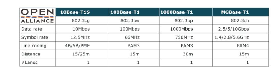
In 2016, the One Pair Ethernet Network (OPEN) committee developed 100BASE-T1 and 1000BASE-T1 automotive Ethernet (subsequently standardized by IEEE), It mainly meets the specific requirements related to electromagnetic interference (EMI) and compatibility (EMC) in automotive applications. The 10BASE-T1S, developed in 2020, enables short-range multipoint network topologies, a feature that makes it ideal for supporting vehicle area architectures. A Gigabit version of automotive Ethernet (MGBASE-T1) is currently being developed. Table 1 lists the specifications for each standard.
Table 1: Automotive Ethernet standards
Protect automotive Ethernet networks
Unlike the Ethernet versions deployed in computing facilities, the 100BASE-T1 and 1000BASE-T1 automotive Ethernet standards use a single unshielded twisted pair (UTP) to connect to the physical layer interface (PHY), as shown in Figure 1. UTP cables are smaller, lighter, less costly and easy to use, all of which are key requirements for automotive Oems, but their construction presents additional challenges for EMI protection.
Figure 1: Automotive Ethernet uses a single unshielded twisted pair

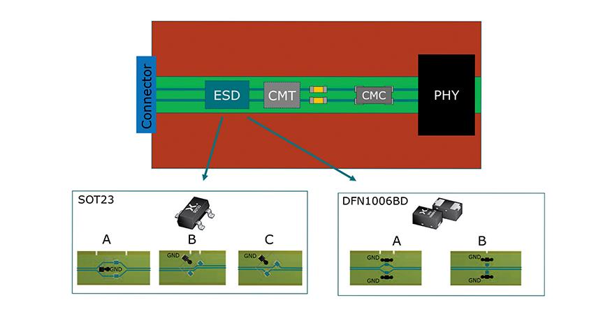
In modern cars, hundreds of meters of cables connect multiple electronic control units (ECUs) that manage various functions. Cables are usually bundled together to form a harness, which greatly increases the likelihood of EMI related problems. In the worst case, EMI voltage amplitudes in UTP cables can be as high as 100 V, so the Ethernet network must be stable enough to withstand these spikes. The protection circuit specified by the Open Technology Alliance for each node in the automotive Ethernet network is shown in Figure 2. This includes a common mode choke (CMC) to filter out unwanted common-mode noise that may be coupled to the cable, while also helping to prevent potentially damaging effects of ESD.
Figure 2: Automotive Ethernet protection circuit specified by the Open Technology Alliance

The key requirement for ESD protection devices is that they should not be activated at voltages below 100 V, while providing ESD protection of at least 15kV for 24 V operating voltages (resistant to at least 1000 discharges). The Open Technology Alliance also recommends that Oems perform a series of additional tests that, while broadly similar for 100BASE-T1 and 1000BASE-T1, have different passing criteria. Two of the tests were designed to measure the impact of ESD protection devices on signal integrity (SI) and to measure insertion loss (IL), return loss (RL), and common mode rejection ratio (CMMR). ESD discharge current testing quantifies the current flowing into the PHY during an ESD event, while RF clamp testing is designed to ensure that the node has electromagnetic compatibility up to 100 V.
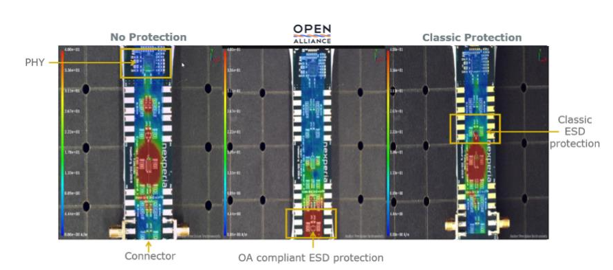
In a real-world automotive Ethernet deployment, the location and layout of ESD protection is critical. As shown in the field scan diagram in Figure 3, this location should be at the connector to ensure that the ESD pulse is directly clamped to ground at the connector to provide maximum protection for all network circuits, including the CMC and PHY.
Figure 3: The impact of an ESD event depends on the layout of the ESD circuit
Under pulsed conditions, CMC can reduce ESD stress on PHY. When the transient pulse hits the CMC, it blocks the current for a period of time, the length of time depends on the voltage level of the pulse, the higher the voltage, the shorter the blocking phase. The blocking phase is followed by the saturation phase, in which the CMC behaves like an inductor entering a saturated state. Once it reaches saturation, it begins to conduct current and the voltage at both ends of the CMC begins to drop. The package wiring of ESD devices should always be kept straight to avoid any contact or bending, and the wiring of differential signals should pass through the solder pad of ESD devices. For the sake of signal integrity, contacts should be avoided and the impedance of the differential line should be 100 Ω. For this, the lines must be separated. Figure 4 shows Nexperia's recommended wiring options for different package types.
Figure 4: Wiring options for SOT23 and DFN packaged ESD protection devices
Nexperia offers a comprehensive line of ESD protection devices for automotive Ethernet
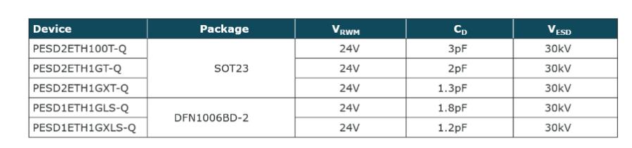
Nexperia offers a variety of ESD protection devices for automotive Ethernet networks (Table 2). The PESD2ETH family of devices is fully compliant with the Open Technology Alliance 100BASE-T1 standard and is packaged in a small SOT23 surface-mounted plastic package designed to protect the two in-vehicle network bus lines from ESD and other transient events. The PESD2ETH1G device complies with the Open Technology Alliance IEEE 100BASE-T1 and 1000BASE-T1 standards and is packaged in small DFN1006BD-2 (SOD882BD) surface-mount plastic.
Table 2:100BASE-T1 and 1000BASE-T1 ESD protection devices from Nexperia
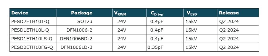
Nexperia also offers highly robust devices that comply with the Open Technology Alliance 10BASE-T1S standard, as shown in Table 3. They have a trigger voltage (Vt) of more than 100 V and low device capacitance (< 0.5pF) for smooth data transmission and excellent signal integrity. For two-wire packages, their capacitance matching specification is 2% (maximum).
Table 3:10BASE-T1S ESD protection device from Nexperia
Conclusion
This article discusses the protection requirements for automotive Ethernet networks and describes board layout options that help improve ESD and EMI stability. Whether implementing 100BASE-T, 1000BASE-T or 10BASE-T1S, automotive Oems can rely on Nexperia to provide the required specifications and form factors for their in-vehicle networks.
About US
Heisener Electronic is a famous international One Stop Purchasing Service Provider of Electronic Components. Based on the concept of Customer-orientation and Innovation, a good process control system, professional management team, advanced inventory management technology, we can provide one-stop electronic component supporting services that Heisener is the preferred partner for all the enterprises and research institutions.