Transmitting data over cables in industrial applications comes with the challenges of a high-transient–voltage environment and high EMC interference. Compact digital isolators can be a solution. For a better understanding of the situation, the application of an industrial intralogistics system with various functional units is used.
Industrial environments, such as warehouses, filling plants, rolling mills or conveyor belt systems, all have one thing in common: They are characterized by a high degree of automation. Temperatures, voltages, speeds and other physical variables are measured by sensors “in the field” and forwarded to a central location. Here, actions are initiated that, for example, reduce the speed of a motor to decrease a temperature reading that is too high. Due to the large space these systems occupy, there can be tens of meters of cable between a sensor and the central control unit.
Figure 1 provides an example of an industrial system, though to scale. Interference-free data communication and personal safety are two major challenges for electronics in this type of industrial environment. Strong electromagnetic fields, surge voltages, transient voltages and high EMC noise are commonplace. If, for example, the communication line is laid unfavorably close to a control line of a frequency converter, the pulses will be capacitively coupled and the signals in the communication line will oscillate with the pulse pattern of the frequency converter.
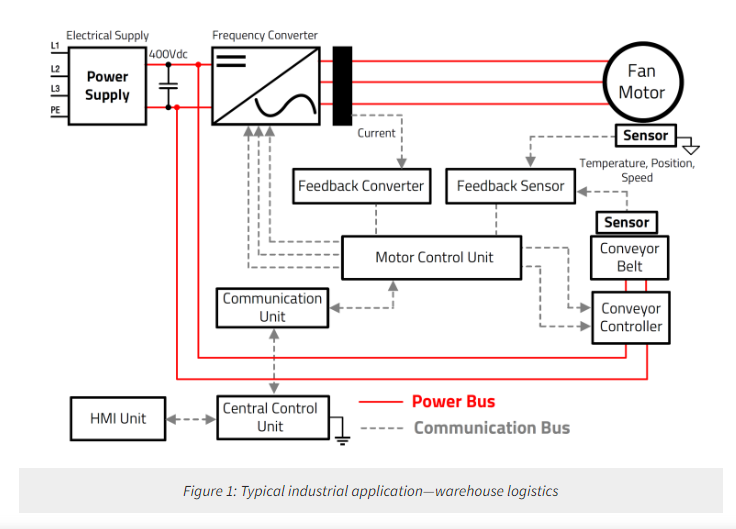
These disturbances can quickly reach a level where significant malfunctions occur and even personal safety can be compromised.For example, when measuring the temperature of a motor using a thermocouple, voltages in the millivolt range are generated. If these voltages are now transmitted over a cable length of several meters to a central control unit that refers to a different ground potential, the measurement signal will be distorted by the potential differences.
Functions of an isolator
Clustering the described phenomena, the following four challenges emerge:
● A safety barrier between hazardous voltages and a user
● Separation of ground loops between spatial circuits
● Minimization of common-mode interference
● Interference-free data transmission
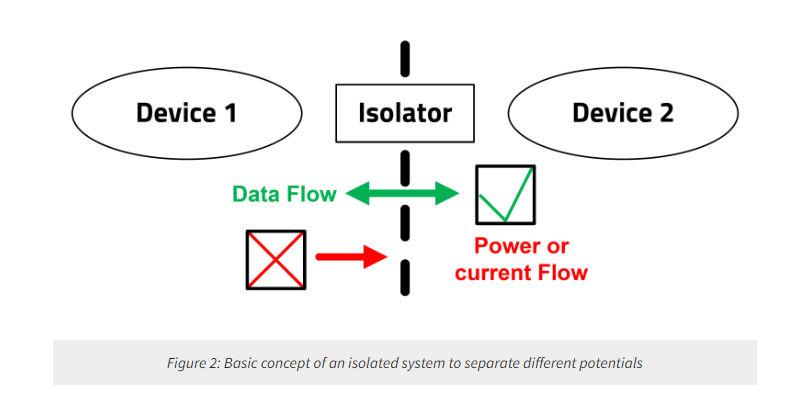
Figure 2 graphically illustrates the situation of the data-transmission system. In order to meet the requirements of blocking dangerous voltages from the user while still guaranteeing interference-free data transmission, galvanic isolation must be used that separates the zones electrically—i.e., their potentials from each other—so that they can work separately and thus without interference.
In general, there are three types of isolation technologies that can be used to separate systems galvanically from each other:
● Optical
● Inductive
● Capacitive
An optocoupler consists of a transmitting LED on the primary side and a phototransistor on the secondary side. Both units are galvanically isolated from each other by an optically conductive medium.
An inductive isolator consists of a primary and a secondary transformer winding positioned at a defined distance from each other. Both windings are galvanically isolated from each other by an insulator, such as a polyimide.
A digital isolator based on the capacitive effect consists of two metal plates separating primary from secondary. Both sides are galvanically separated from each other by an insulating material, such as a polyimide.
All three types of isolators mentioned fulfill the basic requirements of galvanic isolation. However, when we consider the challenges of an industrial application—such as harsh environmental conditions, EMC interference and transient voltages, and data rate—the electrotechnical differences of the three technologies become more significant.
Optocouplers have a limited data-transmission rate inherently due to their transmission technology, LED emission and phototransistor reception. Usually, data rates of a few tens of kilobits per second are possible for standard optocouplers. Data transmission is also very temperature-dependent, as the CTR changes with the temperature.
Depending on how the windings are implemented, inductive isolators can be sensitive to magnetic fields; they then act like antennas and can thus additionally couple interference into the desired signal. Additionally, the insulation material between the primary and secondary windings tends to retain water when exposed to high humidity.
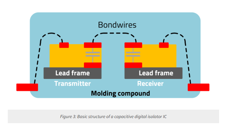
Digital isolators based on the capacitive effect, such as the digital isolators of the CDIS and CDIP series from Wurth Elektronik, are inherently less sensitive to magnetic fields because they use electrical fields for transmission. The structure, shown in Figure 3, enables data-transmission rates of up to 150 Mbps because the capacitors are constructed using a CMOS process. The insulation barrier consists of amorphous silicon dioxide, which is insensitive to humidity.
Please note that this comparison is specifically for the described application and does not claim to be a complete evaluation taking into account all possibilities.
In the next section, we will take a look at the digital isolators of the CDIS and CDIP series from Wurth Elektronik.
Capacitive digital isolators
The digital isolator consists of an oscillator and a modulator on the primary side. On the secondary side are a demodulator and a buffer. The primary-side components are galvanically separated from the secondary-side components by a capacitor structure with an isolation barrier made of SiO2. Signal transmission through the isolation barrier is realized by a modulation method known as on/off keying.
The oscillator integrated in the chip is used to modulate the Schmitt-triggered input signal. The modulator generates a differential signal that is transmitted via the capacitive insulation lines. The demodulator is located on the secondary side and is used to amplify, filter and reconstruct the input signal. The signal delay and distortion are minimal. Finally, the signal from the output of the demodulator is passed through a buffer to the output; the buffer amplifies the signal to the required level. Figure 3 illustrates the internal structure for better understanding.
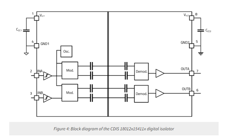
Digital isolators are manufactured using standard CMOS technology and therefore use materials and processes that are well-known and tested. The capacitors of the transmitter side and the receiver side are deposited on a lead frame. The capacitors themselves, shown in gray in Figure 4, are formed between the two horizontal contacts, shown in red. The dielectric material between the capacitor plates serves as a galvanic insulation barrier. The thickness of the insulation achieved by the process is in the range of a few tens of micrometers.
Digital isolators use SiO2 as the insulation material in the capacitor because it requires considerably less space for the insulation gap due to its much higher dielectric strength of 500 V/µm. Other common insulating materials, such as polyimide, have a dielectric strength of only 300 V/µm. The two capacitors are electrically connected with a bond wire so that two capacitors are connected in series, as shown in the block diagram in Figure 4. To protect the entire structure, the die and lead frame are encapsulated by a standard IC molding process.
Wurth Elektronik has recently launched a broad product portfolio of digital isolators that make it possible to cover a wide range of applications (Table 1).
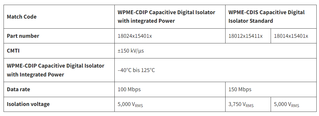
Table 1: Overview of the Wurth Elektronik digital isolator portfolio
All digital isolators are available with either default high- or low-channel–output versions.
Application example: CAN bus
Originally, the controller area network (CAN) bus was developed for automotive applications, but it has become indispensable in industrial plants with functional units that are several tens of meters away. The bus connects the data nodes and the central unit, which takes over the evaluation. Therefore, ground loops can disturb the communication. The CAN bus has a data rate of up to 8 Mbps.
Digital isolators are placed between the CAN transceiver and the local CAN controller (Figure 5). This allows the system to be isolated from the lines. A single external isolated DC/DC power module, such as the FIMM 1769205132, is required as a power supply for both the primary and the secondary side of the digital isolator, maintaining galvanic isolation with only one component. The digital isolators can operate with a supply of 3.3V or 5 V—i.e., both standard logic levels.

Digital isolators and isolated power supplies in combination eliminate ground loops and efficiently protect the system from damage due to overvoltage.
More information about the two-channel digital isolator WPME-CDIS series can be found in the datasheet.1
Application example: SPI Bus
The serial peripheral interface (SPI) bus is a standard for synchronous serial communication designed to provide a simple and low-cost high-speed interface for microcontrollers (MCUs) and peripherals. The SPI bus can transmit at a data rate of up to 60 Mbps over short distances. SPI interfaces are most commonly used for communication between the analog-to-digital converter and MCU. The most common configuration for isolation is three forward channels (CS, SCLK, SDI) and one reverse channel (SDO).
The best solution for this type of task is to use the 18024115401x digital isolator, as shown in Figure 6.
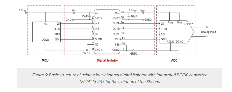
The digital isolator 18024115401x has a three-/one-channel configuration (three forward channels, one reverse channel) and provides an isolation voltage of 5 kVrms and a data rate of up to 100 Mbps. It also has an integrated DC/DC converter, which makes it possible to significantly reduce the number of components in the design and save space on the PCB. In this way, it helps to ensure the required level of isolation and reliable transmission of high-speed signals required when designing an SPI bus.
More information about the four-channel digital isolator WPME-CDIS and WPME-CDIP series can be found in the datasheets.2
Solution for harsh industrial environments
The WPME-CDIS and WPME-CDIP series transmit high-speed digital signals (up to 150 Mbps) safely (VISO up to 5 kV) in harsh industrial environments. In this way, both the signal integrity and the safe functionality of the system can be guaranteed. Digital isolators also offer interesting circuitry possibilities, as will soon be demonstrated by Wurth Elektronik in upcoming application examples, such as for sensors.
About US
Heisener Electronic is a famous international One Stop Purchasing Service Provider of Electronic Components. Based on the concept of Customer-orientation and Innovation, a good process control system, professional management team, advanced inventory management technology, we can provide one-stop electronic component supporting services that Heisener is the preferred partner for all the enterprises and research institutions.